My Big LED Array
Powered by WLED

LEDs are really neat. While I was browsing aliexpress, I found a sale on these flexible 32x8 WS2812 LED panels. I had been playing around with the open-source software project WLED that allows for easy control of addressable LEDs using the ESP family of microcontrollers so I got the idea to buy a few and make a big LED matrix out of them. I also integrated an IMM441 microphone for sound reactive effects.
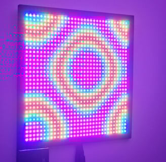
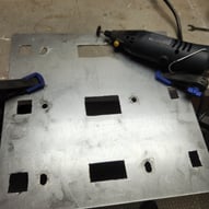
This project involved me doing a lot of things for the first time. I made the frame using a table saw and some scrap wood I found. I used a Dremel to cut the steel backplate that acts as a heatsink and structural support. And I designed a custom PCB to connect everything together. I have been working on this project on and off for about a year and I've been reluctant to actually finish it. Recently I completed the final step and hung it on my wall using drywall anchors. Pictures don't do it justice. 200W of LEDs is quite bright and the colors are very impressive.
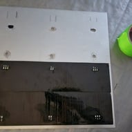
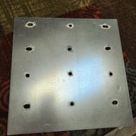
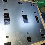
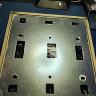
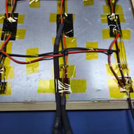
Installing and configuring WLED was very easy thanks to the great documentation on the WLED website https://kno.wled.ge. Once I confirmed all the panels were working and configured correctly, I started sourcing the parts for the rest of the build. At full power, these four panels can draw 60A (32x8x4 LEDs * 60mA per LED) I knew I wanted to run these panels at at least half brightness, so I settled on a 40A 5V power supply I got from Amazon. I also knew that 200W of power would require some heat management, so I decided that a big metal sheet could serve two purposes. My father is in the construction business and asked a friend that installs metal ducting to cut off a square that could fit the panels with a bit of margin on the edges. I secured the panels to backplate with thermally conductive epoxy and the backplate to the frame with regular epoxy.
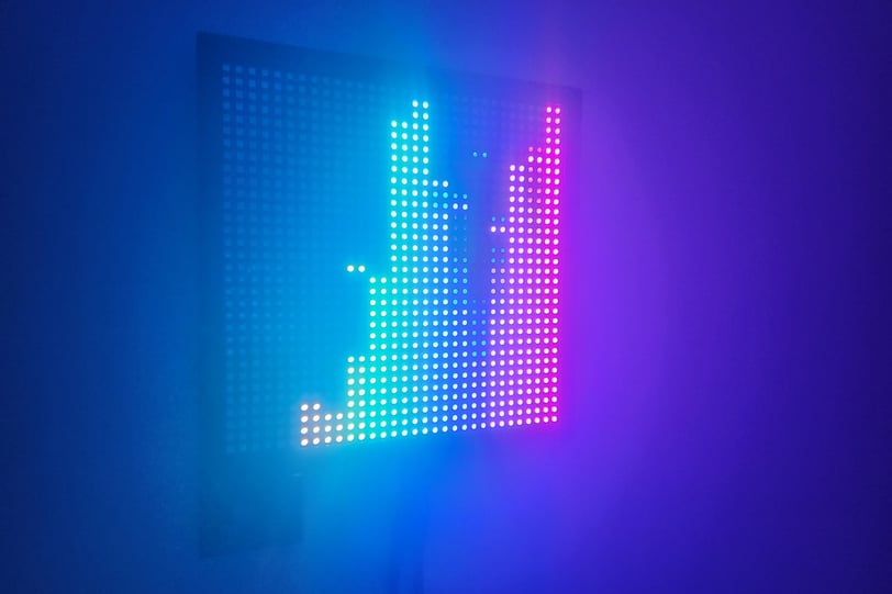
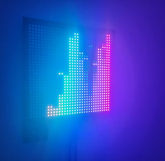
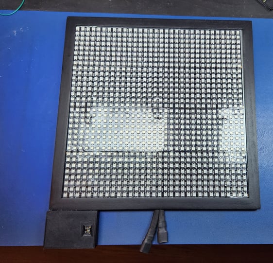
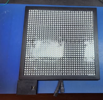
The microphone allows for sound reactive effects like this EQ meter.
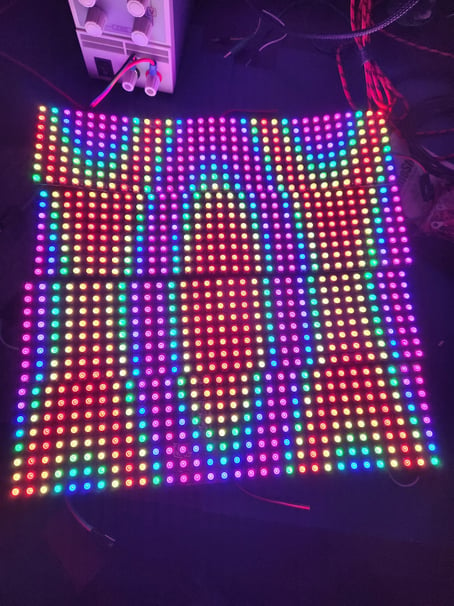
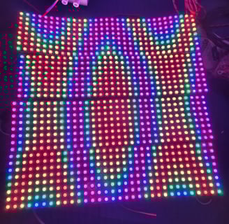
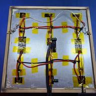
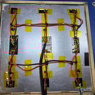
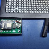
Testing the array.
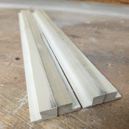
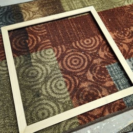
I've made a picture frame only once before, so I spent a lot of time making sure my measurements were correct. Cutting 45 degree angles on a table saw was pretty tricky but I managed to make them mostly square. Cutting the rabbets went surprisingly smoothly.
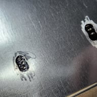
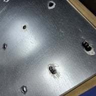
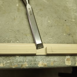
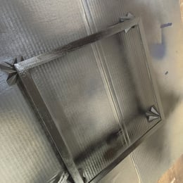
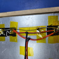
Cutting out holes for wiring using a cutting tool. The first holes I drilled were off slightly.
I've never worked with something drawing so many amps before. I was concerned about choosing the right wire gauge for the current the LEDs were consuming. I erred on the side of caution and purchased some 14AWG which I used for all the wiring in the project. I also picked up some XT30 connectors so I could keep everything modular. Lastly, I made sure to include some fuses on the power lines in case anything goes wrong.
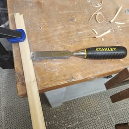
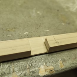
Sharp chisels made cutting the notch out a breeze.
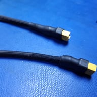
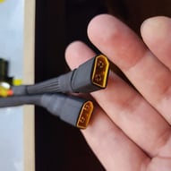
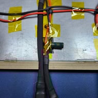
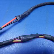
Chonky wiring and connectors. Inline fuses for safety.
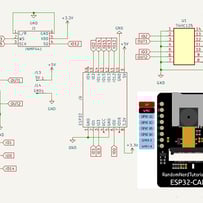
I accidentally purchased a bunch of these ESP32 modules with a camera connector, the ESP32-CAM from AI-Thinker. Not wanting to be wasteful, I was determined to use one these to power my big array. Most of the GPIO on the ESP is connected to the camera and RAM so there's only a few free pins for peripherals. I tested each pin and determined which were available to use to for the LEDs. For best performance, you should run no more than 512 LEDs on a single pin. For my 1024 LED array, I used two pins to drive it.
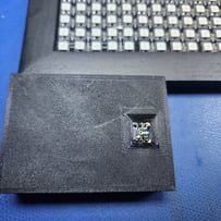
To test the array, I made a circuit on perfboard to connect power and the IMM441 microphone. But I decided to challenge myself and set out to make a custom PCB to act as a carrier and breakout board for the ESP32. The free and open-source software KiCAD was the obvious choice. The learning curve was a bit steep but with some YouTube tutorials I created my first PCB design. I fired it off to PCBWay and 2 weeks later I had my own custom PCBs. Designing and printing a case to hold everything was a simple task but I did go through multiple designs for the lid so that the microphone had a clear opening.
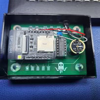
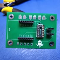
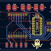
The DIP package is a level-shifter for signal integrity.
Finished product.